
Picking the right PCB Materials is one of those design decisions that looks “manufacturing-focused” at first, but it quietly determines whether your product ships smoothly or turns into a cycle of re-spins, thermal surprises, and signal integrity firefighting. In practice, PCB Materials influence impedance stability, loss at high frequencies, via reliability under thermal cycling, warpage during assembly, and even compliance requirements like flammability ratings.
How to choose PCB base materials without dumbing it down. You’ll learn what matters (and what doesn’t) for real projects, when “standard FR-4” is actually the best choice, and when it’s the wrong choice in disguise.
What “PCB materials” actually means in a real design
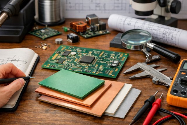
When engineers say PCB Materials, they’re usually referring to the board’s dielectric system (laminates + prepregs) and sometimes the core type (like metal-core). The dielectric system is what sits between copper layers and defines electrical behavior, mechanical behavior, and thermal behavior.
A typical rigid multilayer board uses:
FR-4-class epoxy + woven glass fabric, pressed into laminates (cores) and prepregs (bonding layers). FR-4 is popular because it’s a strong all-rounder and widely supported by fabricators. The IPC specification family that formalizes rigid laminate base materials is IPC-4101.
If you’re designing RF, microwave, very low-loss high-speed, or high-power LED assemblies, you may step outside the FR-4 family into RF hydrocarbons/ceramic-filled systems or even PTFE composites, and for thermal you may use metal-core constructions.
The “big five” properties that should drive PCB material selection
1) Dielectric constant (Dk): impedance and delay stability
Dk influences trace impedance and timing. FR-4 commonly sits around the low-to-mid 4’s depending on resin content, weave, and frequency.
Why it matters: if Dk shifts more than you assumed, your controlled impedance stops being controlled. That shows up as reflections, eye closure, and a board that “almost passes” compliance testing.
2) Dissipation factor (Df): loss at speed and frequency
Df is where many designs get surprised. At higher data rates and RF frequencies, Df becomes a practical limiter on channel reach and margin.
A clear example: Rogers RO4003C is an RF laminate engineered for lower loss and tighter Dk control; typical published values include Dk ≈ 3.38 and Df ≈ 0.0027 at 10 GHz (manufacturer-linked material data is widely cited for this family).
The takeaway is not “always use Rogers.” It’s that Df and Dk tolerance can be the difference between an easy 6-layer stackup and an expensive “why is this failing only on some boards?” situation.
3) Glass transition temperature (Tg) and decomposition temperature (Td): assembly and reliability
Lead-free assembly often pushes higher peak temperatures, and many designs must survive multiple reflow cycles. Standard profiles commonly reference a 260°C peak for Pb-free classification conditions under IPC/JEDEC guidance.
If your laminate system has marginal thermal robustness, you can see measling, CAF risk growth, delamination tendencies, and warpage challenges — especially on larger panels or asymmetrical stackups.
High-Tg FR-4 variants are often the practical step-up. For example, Isola 370HR is commonly described as a ~180°C Tg FR-4 system aimed at higher thermal performance.
4) Coefficient of thermal expansion (CTE): via reliability and fatigue
CTE is a reliability story, especially in the Z-axis. Copper expands roughly ~16–18 ppm/°C, while FR-4 in Z can be much higher, creating cyclic strain on plated through holes (PTHs).
This is one of the most common “it passed functional test but failed after thermal cycling” failure modes in harsh environments. If your product lives in automotive under-hood, industrial temperature swings, or experiences repeated thermal cycling, CTE behavior deserves real attention, not a footnote.
5) Flammability and compliance: UL 94 and safety expectations
Many products must meet specific safety requirements. FR-4 systems are designed as flame-retardant laminates and can achieve UL 94 V-0 ratings in finished form, depending on the system and construction.
If your customer or compliance regime requires specific flammability performance, treat this as a first-class requirement, not something to “check later.”
Choosing PCB materials by application (what tends to work best)
Standard digital and mixed-signal products: when FR-4 is the right answer
If your design is not heavily loss-limited, not thermally extreme, and not operating in harsh cycling environments, standard FR-4 is often the best value. It’s widely manufacturable, cost-effective, and has a large ecosystem of fab experience.
The smarter move here is usually not changing the material; it’s tightening your stackup definition and fab notes. See /pcb-stackup-planning for practical guidance.
High-speed digital (multi-Gbps): when “FR-4” is too vague
For high-speed links, “FR-4” is not a single material. Different FR-4 families vary in Dk/Df and consistency.
If you’re fighting margin on long channels, consider stepping into a mid-loss or low-loss FR-4 family (sometimes still FR-4-class processing), or hybrid stackups where only specific layers use a lower-loss laminate system. Vendor datasheets like FR408HR publish Dk/Df and thermal properties to help you quantify tradeoffs.
A practical scenario: a 10–25 Gbps backplane or long internal cable replacement might “work” on generic FR-4 in the lab but fail in volume because loss and impedance consistency vary more than your design budget allowed. Material control reduces that variability.
RF / microwave: why Df and Dk tolerance matter more than “brand”
For RF and microwave, you care about repeatable Dk and low Df. RO4003C is a common choice because it targets tight dielectric control and low loss while being more process-compatible than PTFE-based systems.
If you’re going even higher frequency or tighter loss budgets, PTFE composites like RT/duroid families are designed for very high-frequency performance and solvent resistance, and their datasheets emphasize stability across frequency ranges.
The real-world tradeoff: PTFE-class systems can raise fabrication complexity and cost. If your fab house isn’t comfortable with PTFE processing, your yield and schedule can suffer even if the electrical performance looks perfect on paper.
High power density and LEDs: when metal-core makes sense
If your limiting factor is heat extraction, metal-core PCB (MCPCB) constructions can reduce thermal resistance dramatically compared to FR-4 for certain geometries, especially in LED boards and power assemblies. Some manufacturing guides cite order-of-magnitude thermal resistance differences depending on dielectric layer conductivity and geometry.
The key nuance: in MCPCB, the dielectric layer’s thermal conductivity is a bottleneck. Many discussions focus on the metal base conductivity, but the thin dielectric is often where the thermal drop happens.
If you’re considering MCPCB, also review /thermal-management for layout, copper spreading, and interface considerations.
A simple decision workflow for smarter PCB material selection
Start with your constraints, not the catalog.
First, define your electrical budget (max insertion loss, impedance tolerance, skew constraints). If you don’t have a quantified budget, you’re guessing, and the “right” material choice becomes luck-based.
Next, define your assembly environment (peak reflow, number of cycles). Pb-free profiles often involve high peaks near 260°C classification conditions.
Then, define your reliability environment (thermal cycling range, vibration, duty cycle). If you have meaningful thermal cycling, prioritize Tg/CTE stability and Z-axis behavior because copper-vs-substrate expansion mismatch is a common fatigue driver in vias.
Finally, apply compliance needs (flammability, safety). FR-4 systems are often chosen specifically because they can achieve UL 94 V-0 in finished laminates, and that matters for many products.
This workflow sounds basic, but it prevents the most common failure pattern: optimizing for BOM cost while accidentally creating a test/compliance cost explosion later.
Fabrication realities that influence material choice more than specs do
Even a perfect datasheet choice can fail if it’s hard to build.
One example: some laminates may not carry the same UL flammability rating expectations as others, or may have different process notes that matter to your manufacturer. RO4003C, for instance, is specifically noted as not UL 94 V-0 rated in manufacturer information.
That doesn’t make it “bad.” It means you must align material choice with the product’s regulatory requirements.
Another common reality: “hybrid stackups” (mixing FR-4 with RF laminates) can be a great cost/performance compromise, but they require careful coordination with the fabricator on bonding systems, drilling/plating processes, and layer registration. You want your fab partner involved early, ideally during stackup definition.
Common questions
What are PCB materials made of?
Most rigid boards use FR-4-class systems: woven glass fabric reinforced with epoxy resin, pressed into laminates and prepregs. These systems are standardized through IPC base-material specifications and are chosen for balanced cost, strength, and manufacturability.
Is FR-4 always good enough for high-speed designs?
Not always. “FR-4” covers a wide range of Dk/Df behaviors and consistency. If your channel is loss-limited or you need tight impedance across production, a controlled low-loss or mid-loss laminate system can reduce variability and improve margin.
What PCB material is best for RF and microwave?
RF designs often prioritize low loss (low Df) and stable Dk. RF laminates like RO4003C are commonly chosen for tighter dielectric control and low loss compared to many FR-4 systems, while PTFE composites like RT/duroid families are used for higher-frequency and very low-loss needs.
Why does CTE matter so much for reliability?
Because copper and the dielectric expand differently with temperature. In Z-axis expansion especially, that mismatch can stress plated through holes during thermal cycling, contributing to fatigue and intermittent failures over time.
Do PCB materials affect safety compliance?
Yes. Many products rely on flame-retardant laminate systems, and finished FR-4 constructions can meet UL 94 V-0 depending on the system and design. Always confirm material and construction compliance needs early.
Practical “smarter design” tips engineers actually use
If your design is borderline, don’t jump straight to the most exotic laminate. First, tighten your stackup definition, control copper roughness assumptions, and make sure your fabricator is building the same dielectric thicknesses you simulated.
If you’re selecting a higher performance FR-4 family (high-Tg or mid-loss), make sure you’re not only improving Tg on paper while leaving Z-axis CTE behavior unaddressed for your environment. Via reliability is often where thermal decisions show up months later.
If you’re going RF, treat dielectric control as a system decision: laminate + process + fab capability. A theoretically great RF material can underperform if the fab process introduces uncontrolled variation.
If you’re going metal-core for thermal, remember the dielectric layer is the thermal choke point. You’re optimizing the entire heat path, not just “using aluminum.”
Conclusion: choosing PCB Materials without overpaying — or under-designing
Choosing PCB Materials is really about matching material behavior to your product’s electrical, thermal, mechanical, and compliance realities. Standard FR-4 remains the best choice for a huge range of products, but high-speed, RF, harsh thermal cycling, and high-power designs often need more controlled laminate systems, higher Tg, better CTE behavior, or different core constructions. When you treat PCB Materials as a design parameter (not a purchasing detail), you reduce re-spins, improve yield, and protect performance margins in production.


Leave a comment